Basic rules for rig operation
1. The operating personnel must be technically trained to understand the structural principle and working performance of the machine, be familiar with the safe operating procedures and maintenance procedures of the machine, and pass the test before they can operate separately.
2. The operating personnel should wear overalls and wear a safety helmet, and the lesbians should stuff the hairpin into the cap.
3. When releasing the gun, the equipment should be retracted to a safe distance and covered and protected; after the shot, a full inspection should be carried out.
4. When encountering winds of more than six levels and freezing, the upper carriage is not allowed. If you really need it, you must fasten your seat belt. It is strictly forbidden to ride on the swing mechanism and slide.
5. If the machine is stopped for a long time, the impactor should be raised outside the hole to prevent the hole from collapsing.
6. When someone is working in the orifice, it is forbidden to supply air to the impactor. When disassembling the drill bit, the swing and lifting mechanism should be closed to prevent injury.
7. The cleaning, oiling, repair and other work of the transmission parts must be carried out under the shutdown condition.
8. Always check the air pipe joints for tightness to prevent injury. The maintenance work of the air supply system must be carried out after the wind is stopped.
9. When landing the carriage, it is not allowed to stay under the carriage.
10. The cable may not be soaked in water or resting on a metal object, the vehicle over the cable, the application isolation protection of wood, to prevent damage to the cable leakage. Wear insulated gloves when handling or moving cables.
11. When drilling, the stop surface should be flat. When working on inclined ground, the wedge block is applied under the track shoe. Horizontal work on slopes is prohibited.
12. At night, there should be sufficient lighting; if the lighting is faulty, stop immediately, and cut off the working power, and continue to work after being repaired.
Second, preparation before starting
1. Comprehensive inspection of all parts of the rig
(1) The welds of each part of the carriage are not cracked, and the connecting screws are not loosened, and the connecting rods of the tensioning device are connected reliably.
(2) The sliding path of the slewing mechanism is moderate, the sliding screw is not loose, the gear transmission is flexible, and the connection of the drill pipe joint, the bearing gland and the hollow main shaft is firm and reliable.
(3) The wire rope of the propulsion mechanism is wound smoothly and properly, the elastic is appropriate, and the brake works reliably.
(4) The transmission belt, chain and track shoes of the traveling mechanism are suitable for tightness, the clutch operation is flexible, and the transmission gear of the carriage landing mechanism is in the disengaged position.
(5) There is no welding or sliding buckle phenomenon in the drill pipe joint. The impactor and the bit are in good condition. The alloy column (sheet) has no phenomena such as desoldering, chipping, and dropping. The drill pipe, impactor and drill bit are connected reliably.
(6) Each operating mechanism is at the stop position and the meter pointer is at the zero position.
(7) Cables and other electrical components are reliably insulated.
2. Fill the lubricating parts with enough lubricating oil and grease.
3. Turn on the power supply, the voltage variation range should not exceed -5 to +10% of the rated value.
4. Connect the air duct, the wind pressure should reach 5 ~ 6 kg / cm 2 . There is no leakage in the pipeline.
5. When performing wet operation, connect the water pipe at the same time, and the pressure should be equal to or greater than the wind pressure. There is no leakage in the pipeline.
6. Safety tools, tools, consumable parts and auxiliary materials are fully prepared.
7. According to the design requirements of the hole position, the azimuth angle of the carriage is correct, and the body is stable and reliable.
Third, rock drilling operation
Counterpoint
(1) The hole position deviation shall not exceed 0.2 m in general, and in case of special circumstances, the maximum shall not exceed 0.4 m. The angle between the holes and the row spacing and azimuth should be as uniform as possible.
(2) Cut off the power of the traveling motor.
(3) Turn on the power of the working system.
(4) Move the main switch of the appliance console to the manual position.
(5) Lift the drill slightly and remove the card wrench on the soldering bracket.
(6) Slowly lower the drill until the drill head is about 30 mm from the ground.
(7) Install the dust cover.
2. Opening, drilling
(1) Start the exhaust fan.
(2) Start the swing mechanism.
(3) Pull the impactor control valve to the half open position.
(4) Turn on the lifting button of the lifting propulsion mechanism and lower the drilling tool. When the bit touches the rock, the impactor begins to work and opens. If a stuck or skew occurs, the drill should be lifted; repeat the above procedure until the impactor begins to drill normally.
(5) According to the condition of the rock, open or pull the impactor control valve to the proper opening position.
(6) Stop the drilling tool, pull the main switch to the automatic position, push the handle of the control valve to the pressure regulating position, and carry out the pressure rock drilling.
(7) If the rock is soft or broken, yellow mud should be placed in the hole to protect the wall.
3. Precautions during normal drilling
(1) Each motor should have no abnormal noise and the temperature rises normally.
(2) The middle gear meshes normally and there is no noise during operation.
(3) According to the rock condition at the bottom of the hole and the current meter reading, adjust the shaft pressure of the drill at any time to avoid overloading the rotary machine. When the current exceeds the rated value, the drilling tool should be submitted immediately, and the inspection can be continued before the operation can be continued.
(4) When the carriage is severely oscillated, the shaft pressure should be reduced.
(5) Stop drilling when the air pressure is below 4 kg/cm2.
(6) The wire ropes of the lifting propulsion mechanism should be arranged neatly, without bridge pressure, and the rope head is firm. Always pay attention to adjusting the tightness of the wire rope.
(7) When a stuck drill occurs, it should be handled according to the specific conditions, and the drill pipe must not be forcibly lifted. In the case of thicker interlayers or water in the holes, it is necessary to first drill and then stop the wind to avoid clogging the impactor.
(8) When the wind pressure suddenly drops and the impactor does not ring, the cause should be ascertained in time.
(9) The limit switch that pushes the cylinder block should be kept flexible and effective to avoid accidents such as overload or broken wire rope.
(10) It is necessary to promptly drain. In the case of soft or broken rock formations, the number of times of lifting and boring should be increased.
4. Connect the auxiliary drill pipe
(1) When the main drill pipe enters the hole and the slewing mechanism reaches the end of the lower end of the carriage, the drilling should be stopped.
(2) Repeat the lifting of the drilling tool (about 1 meter), after blowing the bottom rock powder, stop the supply of air, and then stop the exhaust fan.
(3) Lower the drilling tool so that the upper wrench of the main drill pipe is located about 30-40 mm above the brazing wire, and the spanner is inserted.
(4) Jog the reverse start button of the slewing mechanism to reverse the slewing mechanism by 90 degrees. The main drill pipe is disengaged from the slewing mechanism and is placed on the squeegee.
(5) Raise the slewing mechanism so that the drill pipe joint is slightly higher than the upper end of the auxiliary drill pipe.
(6) Turn the feeder handle to the “I†position (ie the working position) and note that the auxiliary drill rod is sent to the center of the carriage.
(7) Slowly lower the slewing mechanism, insert the drill pipe joint into the auxiliary drill pipe socket, and rotate the slewing mechanism so that the auxiliary drill pipe and the slewing mechanism are fully engaged.
(8) Pull up the rod holder, hold the auxiliary drill rod, slightly lift the swing mechanism, lift the auxiliary drill rod plug from the lower feed rod bracket, and then transfer the handle of the rod feeder to the “II†position. Exit the backstop.
(9) Move the handle handle to the “III†position to release the upper and lower feeds, then pull the handle to the “0†position.
(10) Lower the auxiliary drill pipe, insert the auxiliary drill pipe plug into the main drill pipe socket, and rotate the rotary mechanism to make the main and auxiliary drill pipes fully engaged.
(11) Lift the drill slightly, remove the wrench, lower the bracket, and clean the dust cover.
(12) Start the exhaust fan and the swing mechanism, and open the impactor control valve.
(13) Adjust the shaft pressure and continue normal operation.
5. Unloading the auxiliary drill pipe
(1) When the hole depth reaches the design requirements, raise the drill by about 1 meter. After blowing the rock powder at the bottom of the hole, stop the supply of air.
(2) Lower the drilling tool and check the accumulation of rock powder at the bottom of the hole. The allowable height of the hole shall not exceed 300 mm.
(3) Lift and rotate the drill. When the upper wrench of the main drill pipe is slightly over the brazing, stop the lifting mechanism, the swing mechanism and the exhaust fan.
(4) Insert a wrench into the upper wrench of the main drill pipe and the lower wrench of the auxiliary drill pipe, and manually rotate the main drill pipe 90 degrees (and hold the auxiliary drill pipe at the same time) to disengage the main and auxiliary drill pipes. It should be noted that the slewing mechanism and the auxiliary drill pipe must not be disengaged to avoid accidents caused by the reverse bar. The main drill pipe is dropped and placed on the susceptor.
(5) Raise the rod holder, hold the auxiliary drill rod, and raise the auxiliary drill rod to a position slightly higher than the feeder ring.
(6) Move the lever handle to the “I†position to send the rod feeder to the center of the carriage.
(7) Lower the auxiliary drill pipe so that the plug is inserted into the feedr bracket and check if the backstop falls into the reverse pin hole.
(8) Reverse the swing mechanism by 90 degrees to disengage the auxiliary drill pipe from the swing mechanism.
(9) Pull the joystick handle to the “III†position and exit the auxiliary drill pipe. Then pull the handle to the “0†position.
(10) Lower the slewing mechanism, engage the main drill pipe, slightly raise it, remove the wrench, and raise the hole to the parking position.

Medical Consumables Plastic Mould
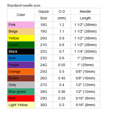
Hospital and medical consumables refers to waste bins, disposable medical syringe, medical disposable bucket and baskets, the molding material is medical grade PP, volume can be different from 1ml, 2ml, 3ml, 5ml, 10ml, 20ml, 50ml, 60ml to 100ml, and needle is 16G-27G, Needle material: stainless steel 304 and life is 5 years. Please review the following specifications in details:
Standard needle size:

Usage:
Tear the single bag of syringe, remove the syringe with needle, remove the syringe needle protection sleeve, pull the plunger back and forth slide, tighten the injection needle, and then into the liquid, needle up, slowly push the plunger to exclude air, subcutaneous or Intramuscular injection or blood.
Storage condition:
Disposable Medical Plastic 2 ml Syringe Luer Slip store in the relative humidity not to surpass 80%, non-corrosiveness gas, cool, ventilates good, in dryly the clean room. Product sterilized by Epoxy hexylene, asepsis,non-pyrogen without unusual toxicity and hemolysis response.
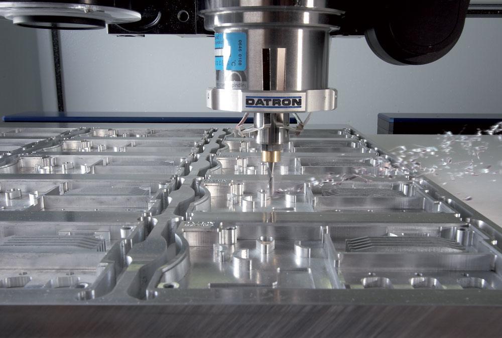
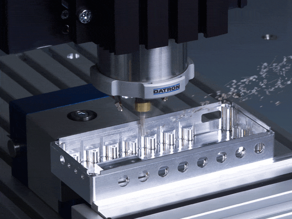
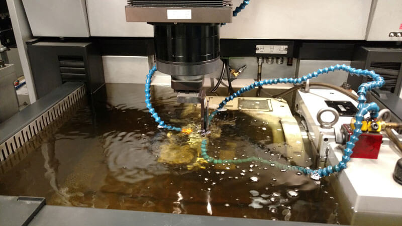
Machining equipment:


FAQ:
Q1: How do you control quality of Disposable syringe mould quality?
A: We use our CMM measuring equipment to inspect mould critical dimensions and mould tryout sample parts, all dimension reports will be shared with customer and discussed with customer the best solutions to solve "NG" dimensions.
Q2: What are the MOQ and leading time?
A: 200000pcs each type; leading time is within 35 days or based on your quantity;
Q3: What are the terms of payment?
A: 50% in advance by T/T; the balance 50% by T/T before shipping or again copy of B/L, L/C are acceptable.
Q4: How to keep us away from risk?
A: Our manufacturing is with rules of CE, ISO, welcome to visit our factory, and we can send you samples before placing an order.
Medical Consumables Plastic Mould,Metal Injection Molding,Medical Syringe Plastic Injection Mould,Disposable Syringe Plastic Injection Mould
Zhejiang Ceeto Molding Technology Co.,Ltd. , https://www.ceetomold.com