Shaft frame steel device seat layer cutting assembly machine
First, the determination of the processing plan
The front axle is a slender, shaped rod-like part with the same accuracy and requirements as shown. The two leaf spring seat faces are coplanar and the flatness is less than 0.025, and the surface roughness value is less than Ra6.
3; The distance between the two leaf spring seats is 820~900mm. The machining method is milling, interrupted cutting, large vibration and high noise. These are the main factors that reduce the machining accuracy and surface roughness of the front axle. The two leaf spring seat faces are the positioning base surfaces of the subsequent process; the plane formed by the center of the two punches and the twisting degree of the spring seat surface are the key to ensure the uniformity of the wall thickness of the king pin hole. The front axle blank is a die forging, and the machining allowance of the split mold high point is about 15mm. According to the processing principle of the front face back hole, it is very difficult to complete the one-time machining; if the roughing and milling is performed with one clamping, the expected result will be less than expected. Effect (no self-release time of internal stress caused by cutting; if using secondary clamping, how to achieve reasonable difficulty), such as increasing the finishing process will increase unnecessary process costs. Therefore, the circular arc surface with one end of the fist is positioned with a fixed V-shaped block, and the other end is positioned with the movable V-shaped block to ensure that the plane formed by the center of the two fists is twisted with the plane of the leaf spring seat to control the uneven wall thickness of the main pin hole. The position of the I-shaped blank surface of the leaf spring seat is selected and clamped, and the floating self-supporting is adopted; the clamping points are respectively the side faces of the two leaf spring seats, as shown in 2.
Second, the structure and adjustment of the machine tool
The machine tool is a two-axis vertical milling machine for milling a variety of front axle leaf spring seats. For example, it can complete EQ140, EQ150, EQ153 and other leaf spring seat surface machining, mainly from base, column, milling head, moving table, cross slide, It consists of fixtures, tools, hydraulic systems, gas-electric liquid control systems, and centralized lubrication devices. The two hydraulic pressures allow the cutter milling head to be mounted side by side on the cross slide. The position adjustment is determined according to the position and size of the steel seat surface. The center distance of the two milling heads (range 690~1000mm) is adjusted by the lateral movement of the screw by the hand wheel. Locking the slide plate fastening screw to realize the processing of the front axle leaf spring seat surface of different specifications; the extension length adjustment of the milling head spindle is manually adjusted by the screw on both sides of the milling head to achieve the milling plane coplanar of the left and right milling cutters After the adjustment is completed and locked; the machine tool is a machine-clamp type non-grinding milling cutter disc, the blade does not need to be sharpened, and the cutting blade can be used after clamping; the feed motion is completed by the moving table, the feed speed The moving front suspension wheel is adjusted by the moving front axle two leaf spring seat surface milling combined machine tool table, which is adjusted at the factory, generally does not need to be adjusted, the feed distance is controlled by the electric switch arm control; the machine tool fixture is installed on the mobile On the workbench, the working principle and adjustment of the fixture are described in the description; the machine tool adopts gas, electricity and liquid systems, which are controlled by PLC, and the working cycle of the machine tool is 4.
Third, the structure of the fixture
The clamp adopts the split combination adjustable jaw type structure as shown in 5 and 6; the working principle of the front axle positioning and clamping is that the circular arc surface of the fist is fixed by the fixed limit jaw, that is, the V seat on the limit seat 1 Block 2 is positioned, one end uses a limit cylinder to push the V-shaped block 16 to position the arc surface of the fist; two adjustable support pins 10 are mounted on the U-shaped frame 9 under the two leaf spring seat faces, and the U-shaped frame 9 can be The arcuate groove of the U-shaped seat 8 floats to realize the automatic adjustment of the positioning surface; the front side jaw is the limiting jaw 14 , and the limiting cylinder 6 pushes the limiting jaw 14 to the side of the steel plate surface, and the rear side is movable. The jaw 15 is pushed by the clamping hydraulic cylinder 5 to realize the clamping force; the limiting cylinder and the clamping cylinder are arranged on the side of the two steel plates respectively, and the positions of the jaws, cylinders and cylinders can be visualized as the front axle specifications, and can be clamped The T-slot movement of the bottom plate is adjusted; the adjustable support nails are not constantly adjusted during processing, and the work efficiency is improved. The cylinder pressure is between 0.2 and 0.
3MPa is suitable, after the two limit jaws are fed, the workpiece is not pushed. When the system clamping pressure is 4MPa, the cylinder output force is 2000Kg. After the 1:5 slope wedge force is applied, the clamping force is about 10000Kg. This fixture has high and stable quality requirements for the workpiece blank. The cylinders and cylinders such as positioning, limit and clamping of the fixture are controlled by PLC, interlocking gas, liquid and electricity, and the operation cycle is reliable. When processing the front axle of other specifications, based on the selected specimen, firstly position the arc of the fist of the specimen, adjust the position of the left and right limit seats 1, 7, the steel plate surface and the two pin punch hole The plane formed by the center is vertical, ensuring uniform wall thickness of the main pin holes on the two fists. Then adjust the position of the limit jaws 14, the clamping jaws 15 and the corresponding cylinders and cylinders; then adjust the distance between the two milling heads, and respectively mill two planes separated by 690-1000 mm to ensure the two leaf spring seats The flatness requirement, the size of the sample piece is adjusted by the two milling head spindle sliding sleeves, and the machining requirements can be processed to process the workpiece.
End
The machine tool better solves the processing of the front axle leaf spring seat surface, overcomes the disadvantages of the original machine tool rigidity, vibration, noise, and adjustment complexity, and improves the work efficiency while ensuring the processing quality, and has a high Economic benefits and application value. The machine tool has been accepted and delivered for use, and the quality of its processed products is stable and reliable, which has been well received by users.
(Finish)
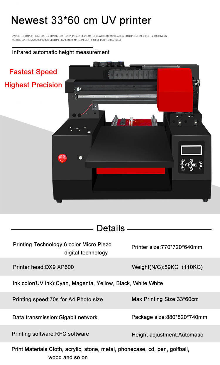
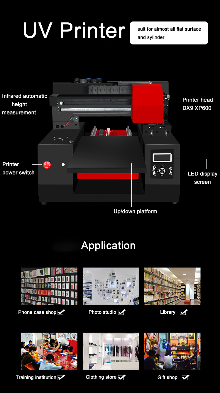
UV printer is a kind of "non-contact" ink jet type digital equipment, uv printer application is very extensive. Using the devices supporting the UV ink, in addition to the fabric can't print, uv printer can printing almost all other material (mobile phone cover, leather, signs, light boxes, mobile power supply, Flash memory disk, KT board, stone, silica gel, wood, ceramic, crystal, acrylic, PVC, ABS etc.) material can be color printing, finished with scratch resistance, wear resistance, resistance to fade. To achieve a true sense of a seal, no plate, spray dry, a complete color image.


UV Printer is the latest UV machine of refinecolor company . This model is designed for industrial bulk production with high printing speed, which can print on almost any material directly .With UV light irradiating during printing procedure, images on object surface are dry fast and Scratch resistance.
UV Printer,Small UV Printer,A3 UV Printer,Mini UV Printer,A4 UV Printer,A2 UV Printer
Shenzhen Refinecolor Technology Co., LTD. , https://www.szfoodprinter.com