Flow Sensors
The air flow sensor is a sensor that measures the flow of air drawn into the engine. Electronically Controlled Gasoline Injection A flow sensor system is required to measure the amount of air taken into the engine at each moment in order to obtain the optimum concentration of the mixture in all operating conditions. The main basis. If the air flow sensor or the line fails, the ECU cannot obtain the correct intake air quantity signal, and the control of the fuel injection amount cannot be normally performed, which will result in the mixture being too rich or too lean and causing the engine to operate abnormally.
Verification procedures and flow meter standards are the guarantee that the flow sensor can accurately measure. In many areas, the accurate measurement of traffic is very important, and it is widely used in the economic field, such as: environmental monitoring, health care, security protection, and trade settlement.
According to the structure of the flow sensor can be divided into the blade (wing) type, measuring core type, hot line type, hot film type, Karman vortex type and so on.
Classified according to their standard nature, can be divided into the following categories. Method standard: Calculation method, detection method, test method and performance evaluation method of some sensors, etc.; Basic standards: Basic parameters of the specifications of some sensors, models, nomenclature, and professional terminology in the measurement process; Product standard: this class Sensors have been quickly and easily included. They specify the technical requirements of the sensors, acceptance rules, test methods, and product classification. In addition, there are requirements for proper installation and use. Some standards only have the correct installation and use technologies. These are the nature of product applications in product standards.
If divided according to Chinese standards, they can be divided into four major categories: corporate standards, local standards, industry standards, and national standards.
1) Classification by input quantity: displacement sensor, speed sensor, temperature sensor, pressure sensor, etc.
2) Classified by working principle: strain gauge, capacitive, inductive, piezoelectric, thermoelectric, etc.
3) Classification by physical phenomena: structural sensors, characteristic sensors
4) Classification by Energy Relationship: Energy Conversion Sensor, Energy Control Sensor
5) Classification by output signal: analog sensor, digital sensor [1]
Small size, light weight, intuitive and clear display readings.
High reliability, unaffected by external power supply, lightning strike resistance.
Currently, the baffle can be designed according to the size of the water flow to reduce the water resistance generated by the flow of water through the flow sensor and reduce the head loss of the water system. However, due to the long-term impact of the flow of the baffle, there is still a problem of fatigue, even if the flow rate is calibrated at the factory. Setpoint drift also occurs for values.
It is usually used where the protection flow value is not required to be precise, ie, the cut-off protection for sudden interruption of the water flow in the water pipe. There are very few designs for water source heat pump units in China.
The baffle type is specially developed for water flow monitoring of water ring/ground source heat pump air conditioning units. It is equipped with different baffle plates for different pipe diameters. The water resistance of each baffle plate is not more than 0.5 m water column. Target water resistance has been greatly reduced.
Each baffle type flow sensor is equipped with the same pipe fitting as the water ring heat pump unit water pipe, and the site only needs to connect the water pipe, without any change to the baffle, and the pressure of the baffle type water flow switch is greater than 25 bar. The water ring heat pump unit, which does not require high water flow, is a low-cost water flow switch.
According to the feedback used on the water ring/ground source heat pump unit, the pressure difference switch can effectively determine the problem of the water pipe installed on the water ring heat pump unit at the site, and can completely avoid the situation in which the heat exchanger is frozen and the flow rate is small due to the small water flow. The sensor can also protect the heat exchanger from freezing when the flow rate of water is reduced due to the blockage of the water Filter. In addition, the water line pressure difference switch does not have the risk of fatigue failure of the target switch.
In particular, when there is a small amount of air in the water pipeline, the flow sensor operates very stably, and there will be no floating situation similar to the target flow switch. After years of feedback, the differential pressure switch itself has not been found to be faulty.
Temperature installation method
1. One-time metering system: This installation situation means that in the entire heating system, there is only one metering system.
2. Secondary metering system: The difference from the primary system is that the metering at the installation location belongs to the second metering.
3. Individual heating measurement in home users: With the popularization of household metering and the promotion of heating and energy saving engineering, this kind of installation method is currently common.
4. Vertical heating distribution metering: Mainly used for heating metering in vertical heating systems.
Basic Principles and Types of Ultrasonic Flowmeters Ultrasonic waves carry information about the flow rate of a fluid when it travels in a flowing fluid. Therefore, the flow velocity of the fluid can be detected by the received ultrasonic wave and converted to flow.
According to the detection method, it can be divided into different types of ultrasonic flowmeters such as the differential propagation velocity method, Doppler method, beam offset method, noise method, and correlation method. The sonic wave flowmeter is a non-contact type instrument that began to be applied with the rapid development of integrated circuit technology in the past ten years and is suitable for measuring fluids that are difficult to contact and observe, and large-diameter flow. It works in conjunction with a water gauge to measure open flow. The use of ultrasonic flow ratio does not change the flow state of the fluid without installing a measuring element in the fluid, and no additional resistance is generated. The installation and overhauling of the instrument does not affect the operation of the production line and is therefore an ideal energy-efficient flow meter.
Industrial flow measurement has the problem of large diameter and large flow measurement difficulties. This is because general flowmeters have difficulties in manufacturing and transportation as the diameter of the measurement increases. The cost is increased, the energy loss is increased, and the installation is not limited. With these drawbacks, ultrasonic flowmeters can be avoided. Because all types of ultrasonic flowmeters can be installed outside the pipe, non-contact flow measurement, the instrument cost is basically irrelevant to the size of the measured pipe diameter, while other types of flowmeters increase with the diameter, the cost increases significantly, so the larger the caliber ultrasonic The flowmeter has a superior function to price ratio over other types of flowmeters with the same function. Considered to be a good large-diameter flow measuring instrument, the Doppler ultrasonic flowmeter can measure the flow of the two-phase medium, so it can be used for the measurement of dirty streams such as sewers and sewage. In power plants.
Fluid propertiesFluid type fluids are classified into liquids, gases, and steam. Some sensors (such as electromagnetic) cannot measure gas; inserting heat does not measure liquid.
Temperature, pressure, density They are important parameters provided by the choice of sensors, especially parameters under operating conditions, for the gas flow should also understand whether the volume flow is the working state or the standard state.
Viscous liquid viscosity difference will affect the selection, such as the viscous liquid should use volumetric flow sensor, but not suitable for the use of turbine, float, vortex flow sensor.
Corrosion, scale, and dirt For such fluids, sensors with rotating parts and sensors are not suitable. Even for ultrasonic, electromagnetic flow sensors, errors can be caused by corroding the pipes. Such as caliber 50MM, scaling 0.5 ~ 1MM, will bring 0.5 to 1% error.
Special Parameters Certain fluid parameters can affect the operation of the sensor, such as the compressibility coefficient affecting the differential pressure type; specific heat and thermal conductivity affect the thermal type; the electrical conductivity affects the electromagnetic; and the sound velocity affects the ultrasonic.
Single-phase and multi-phase refers to substances that have the same physical and chemical properties in one system. Different phases have more obvious interfaces. Usually, most of the industries are single-phase. As the industry develops, multi-phase flow occurs ( Flow measurement problems such as gas-solid, gas-liquid, liquid-solid or gas-solid-liquid).
The state of the flowUnlike many physical parameters (such as pressure, temperature, level, and composition), the flow must be based on fluid flow. Without flow, there is no flow.
Full-pipe and non-full-pipe general fluids should be filled with pipes. However, when the liquid flow is small and the pipes are in level, there may be non-full pipe flow. There are already non-full pipe flow sensors.
Technical ParametersThe total amount and total flow (in units of M3 or KG) are mostly used for trade accounting, and the accuracy is at the top. The flow rate (instantaneous unit is M3/H, KG/H) is mostly used in the process industry and is the source of information for the control system. Repeatability is the highest priority.
Continuously, the output of the switching general flow sensor is a continuous amount, and the switching amount can be used for simple two-position control or equipment protection, and the reliability is required to be good.
Accuracy accuracy depends not only on the sensor itself, but also on the verification system, which is an additional feature. To explain the accuracy of the flow range, if used in the control system, it should also be considered to match the accuracy of the entire system. Note: The error noted by the manufacturer is %FS (upper limit); or %RD (measured).
Repeatability repeatability refers to the consistency of multiple measurement of a certain flow value when the environmental condition medium parameters are unchanged, which is the characteristics of the sensor itself. In process industry control systems, repeatability is often more important than accuracy. Many manufacturers mislead reproducibility into accuracy. Accuracy should include repeatability and flow uncertainty of the calibration device.
The range ratio is within a certain range of accuracy, the ratio of maximum to minimum flow. Differential pressure flow sensors, from the sensor itself can have a large turndown, but subject to the constraints of the secondary table, generally only 3:1.
Pressure loss flow sensors (except for electromagnetic, ultrasonic) have sensing elements (such as orifices, turbines, etc.), and forced changes in flow direction (such as elbow, Coriolis) will generate irrecoverable pressure loss, which will increase the power of the transmission In order to maintain normal operation, some amounts are very large, and we should pay attention to promoting energy conservation today.
The output signal is generally a standard analog signal (0 ~ 10V, 4 ~ 20MA, etc.) has not been able to adapt to system development requirements. Communication requires digital signals, ROSEMOUNT introduced HART protocol, RS232/RS485 converter, RS232 is limited to 2KM, RS485 up to 10KM.
Response time The output signal reacts with the change of the flow parameter, the shorter the better for the control system, and the slower output response for the pulsating flow.
The performance indicators of the comprehensive performance sensor are mutually restrictive. For example, the upper pressure limit in the sample is 2MPA; the temperature is 250°C, and the caliber is 1M; when the caliber is 1M, the pressure may only be 1.5MPA and the temperature may only be 200°C. It is not possible to be the limit value.
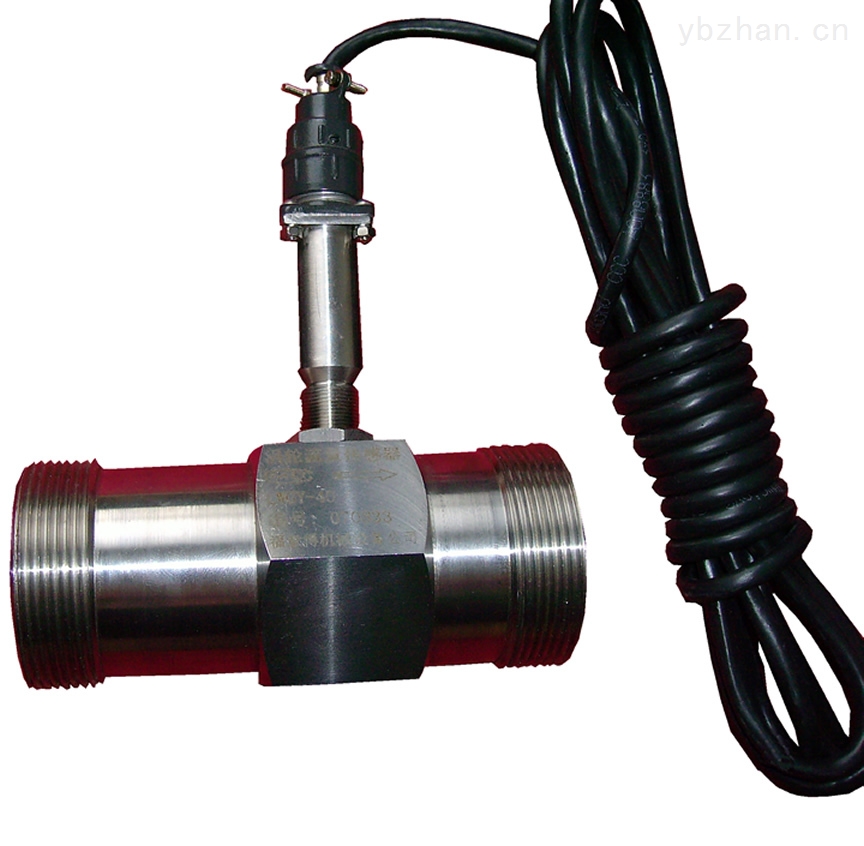
1, water flow sensor
The water flow sensor is mainly composed of a copper valve body, a water flow rotor assembly, a steady flow component, and a Hall element. It is installed at the water inlet of the water heater to measure the flow of incoming water. As water flows through the rotor assembly, the magnetic rotor rotates and the rotational speed changes linearly with flow. This product has been quickly and easily included in the Hall element output corresponding pulse signal feedback to the controller, by the controller to determine the size of the water flow, adjust the current control proportional valve, so that the proportion of gas flow control valve to avoid the use of gas water heater During the process, the phenomenon of summer warm and cold in winter appeared. The water flow sensor fundamentally solves the disadvantages of the high water pressure of the differential pressure type water and gas linkage valve and the proneness of the flap water valve to malfunction. It has the advantages of being sensitive, long life, quick action, safe and reliable, and easy connection and low flow (1.5L/min). It is well received by users. [2]
2, plug-in type flow sensor
Plug-in flow sensor working principle is based on Faraday's law of electromagnetic induction. In the electromagnetic flow sensor, the conductive medium in the measuring tube corresponds to the conductive metal rod in the Faraday test, and two electromagnetic coils at the upper and lower ends generate a constant magnetic field. When there is a conductive medium flowing, an induced voltage is generated. Two electrodes inside the pipe measure the induced voltage generated. The measuring pipe is electromagnetically isolated from the fluid and the measuring electrode by a non-conducting inner lining (rubber, Teflon, etc.). [3]
The structure, working principle and detection of vane type air flow sensor The traditional Bosch L type gasoline injection system and some mid-range models use this type of vane type air flow sensor. It consists of an air flow meter and a potentiometer. The air flow meter has a rotary fin (measurement piece) swingable around the shaft in the intake passage, and a coil spring acting on the shaft allows the measurement piece to close the intake passage. When the engine is running, the air intake airflow passes through the air flow meter to push the deflection of the measuring plate to make it open. The size of the opening angle of the measurement piece depends on the balance between the thrust of the intake air flow on the measurement piece and the spring force of the coil spring on the measurement piece axis. The amount of intake air is changed by the driver operating the throttle. The larger the intake air volume, the greater the thrust of the air flow on the measurement piece and the larger the opening angle of the measurement piece. A potentiometer is attached to the measurement spool, as shown in Figure 3. The slide arm of the potentiometer rotates synchronously with the measuring piece coaxially, converting the change in the opening angle of the measuring piece (ie, the change in the amount of intake air) into a change in the resistance value. The potentiometer is connected to the ECU through wires and connectors. The ECU measures the air intake of the engine based on the amount of change in the resistance of the potentiometer or the amount of change in the voltage applied to it.
In the vane type air flow sensor, there is usually an electric petrol pump switch. When the engine starts running, the measuring piece is deflected, the switch contact is closed, and the electric petrol pump is energized; after the engine is turned off, the measurement piece is turned to the closed position and the electric gasoline pump switch is turned off. At this time, the electric petrol pump does not work even if the ignition switch is in the open position.
The flow sensor also has an intake air temperature sensor that measures the intake air temperature and compensates for the intake air temperature.
Blade type air flow sensor wire connector generally has 7 terminals. However, the electric gasoline pump control contact switch inside the potentiometer is also cancelled and becomes five terminals. Nissan and Toyota Automotive Blade Air Flow Sensor Wire Connector Terminal "mark." Its terminal "mark" is generally marked on the connector's jacket.
VortexVortex flow sensor is mainly used for the flow measurement of medium fluids in industrial pipelines, such as gases, liquids, vapors and other media. Its characteristics are low pressure loss, large range, high precision, and almost no influence of parameters such as fluid density, pressure, temperature, and viscosity when measuring volume flow. No moving mechanical parts, so high reliability and low maintenance. Instrument parameters can be stable over a long period of time. The vortex flow sensor uses a piezoelectric stress sensor with high reliability and can work in the operating temperature range of -20°C to +250°C. There are analog standard signals and digital pulse signals output. It is easy to use with digital systems such as computers. It is a relatively advanced and ideal measuring instrument.
The vortex flow sensor is developed based on the Carmen vortex principle. When a triangular column-type vortex generator is provided in the fluid, a regular vortex is alternately generated from both sides of the vortex generator. This vortex is called a Karman vortex.
Let the frequency of vortices be f, the average flow velocity of the medium to be measured, the width of the inflow surface of the vortex generating body be d, and the diameter of the body is D, the following relationship can be obtained:
f=SrU1/d=SrU/md (1)
In the formula U1--average velocity of the vortex generating body, m/s;
Sr-- Strouhal number;
M--ratio of the arch area on both sides of the vortex generating body to the cross-sectional area of ​​the pipeline
The volume flow qv in the pipe is qv=Ï€D2U/4=Ï€D2mdf/4Sr (2)
K=f/qv=[Ï€D2md/4Sr]-1 (3)
In the formula K--flowmeter meter coefficient, pulse number /m3(P/m3).
It can be seen from the above equation that the output frequency of the flow sensor is only related to the shape and size of the vortex generating body and the pipeline.
Carmen vortexThe structure and working principle of the Karman vortex air flow sensor are shown in Figure 11. In the middle of the intake duct, there is a first-class linear or triangular vortex generator. When the air flows through the vortex generator, an asymmetric but very regular air called Karman vortex is continuously generated in the air flow behind it. vortex.
There are two methods for measuring the number of vortexes per unit time: the Mirror detection type and the ultrasonic detection type. It is a mirror-detected Karman vortex flow sensor with a light-emitting diode and a phototransistor. The light beam emitted by the light emitting diode is reflected by a reflector on the phototransistor, which turns on the phototransistor. The mirror is mounted on a thin metal reed. The metal reed generates vibration under the pressure of the vortex of the intake air flow, and its vibration frequency is the same as the number of vortices generated per unit of time. Since the reflector vibrates with the reed, the reflected beam also changes at the same frequency, so that the phototransistor also turns on and off at the same frequency as the beam. The ECU calculates the intake air volume based on the frequency of the phototransistor conduction and cut-off. The Lexus LS400 passenger car uses this type of Karman vortex air flow sensor.
Figure 13 shows an ultrasonic detection type Karman vortex air flow sensor. On both sides of the second half there is an ultrasonic transmitter and an ultrasonic receiver. While the engine is running, the ultrasonic transmitter constantly emits ultrasonic waves of a certain frequency to the ultrasonic receiver. When the ultrasonic wave reaches the receiver through the intake air flow, the phase of the ultrasonic wave changes due to the influence of the vortices in the air flow. The ECU calculates the number of vortices generated per unit time based on the frequency of the corresponding change detected by the receiver, thereby obtaining the air flow rate and flow rate, and then determining the reference air amount and the reference ignition advance angle based on the signal.
HotlineThe basic structure of the hot air flow sensor consists of a platinum hot wire (platinum metal wire) that senses the air flow, a temperature compensation resistor (cold wire) that is corrected based on the intake air temperature, a control circuit board that controls the hot wire current and produces an output signal, and air flow. Sensor housing and other components. According to the installation location of the platinum hot wire in the housing, the hot air flow sensor is divided into two main forms of measurement: mainstream measurement and bypass measurement. FIG. 18 shows the structure of a hot air flow sensor using a mainstream measurement method. It has metal protection nets at both ends. The sampling tube is placed in the center of the main air channel. The sampling tube is composed of two plastic sheaths and a hot wire support ring. The platinum wire (RH) with a hot wire diameter of 70 μm is arranged in the support ring. Its resistance value changes with temperature and is an arm of the Wheatstone bridge circuit. A platinum thin film resistor is installed in the plastic sheath at the front end of the hot wire support ring. Its resistance value changes with the intake air temperature and is called the temperature compensation resistance (RK). It is the other arm of the Wheatstone bridge circuit. A precision resistor (RA) is attached to the plastic sheath at the rear end of the hot wire support ring. This resistor can be laser trimmed and is also an arm of the Wheatstone bridge. The voltage drop across this resistor is the output signal voltage of the hot air flow sensor. Wheatstone bridge also has an arm resistor RB mounted on the control circuit board.
Working principle: The hotline temperature is kept by the hybrid integrated circuit A at a certain value from the intake air temperature. When the air mass flow increases, the hybrid integrated circuit A increases the current through the hot wire, and vice versa. In this way, the current through the hot line RH is a single function of the air mass flow, ie the hot line current IH increases with the increase of the mass air flow, or decreases with it, and generally varies between 50-120 mA.
The application in the ventilator has been used for nearly 30 years and is commonly used in middle and high grade ventilators. As an important component of the ventilator air system, it is responsible for converting the inhaled and exhaled gas flow into electrical signals, which are sent to the signal processing circuit for detection and display of inhaled and exhaled tidal volume, minute ventilation, and flow rate.
According to the different functions and designs of the ventilator, the detection value of the flow sensor not only provides display, but also plays a decisive role in the control and alarm of the ventilator, such as the flow sensor feeding the measured actual value to the electronic control part and the panel setting. The value comparison uses the error between the two to control the servo valve to adjust the inhaled and exhaled gas flow; signals generated by the air and oxygen flow sensors installed at the front of the inhalation system can help the microprocessor to control the valve to provide the patient with the required Oxygen concentration; flow rate and flow detection value also directly affect the switching of exhalation and inspiration phase, minute ventilation limit alarm, flow trigger sensitivity, real-time flow waveform and PV-ring monitoring display, etc. Sensor performance directly affects the accuracy and reliability of the ventilator parameters.
Technological innovationThe global sensor market is showing rapid growth among the ever-changing innovations. Relevant experts pointed out that the major technologies in the field of sensors will be extended and improved on an existing basis. Countries will compete to accelerate the development and industrialization of new generation sensors, and competition will become increasingly fierce. The development of new technologies will redefine the future market of sensors, such as the emergence and market share of new sensors such as wireless sensors, fiber optic sensors, smart sensors and metal oxide sensors.
ProspectsThe sensor market report shows that in 2008, the global sensor market capacity was 50.6 billion U.S. dollars, and the global sensor market is expected to reach more than 60 billion U.S. dollars in 2010. The survey shows that Eastern Europe, Asia Pacific, and Canada have become the fastest growing areas for the sensor market, while the United States, Germany, and Japan are still the most widely distributed areas for the sensor market. Worldwide, the fastest-growing sensor market is still the automotive market, the second is the process control market, optimistic about the communications market. Some sensor markets such as pressure sensors, temperature sensors, flow sensors, and level sensors have demonstrated the features of a mature market. Flow sensors, pressure sensors, and temperature sensors are the largest in the market, accounting for 21%, 19%, and 14% of the entire sensor market. The major growth in the sensor market comes from emerging sensors such as wireless sensors, MEMS (Micro-Electro-Mechanical Systems) sensors, and biosensors. Among them, the wireless sensor's compound annual growth rate in 2007-2010 is expected to exceed 25%.
Therefore, when selecting a flow sensor, the user should select an appropriate sensor according to his own needs. Many users have different requirements for the sensors used, so the standards chosen are also different. If you need very professional data and results, you should select national standards. However, if you only want to analyze it as a simple instrument in your company, you can select enterprise standards. If you want to buy a flow sensor, we must carefully consider, and choose some quality assurance, better use of the sensor. Because many people think that new sensors, their technology will be higher, this is a one-sided idea. New products must have mature technologies to be good products.
In many economic fields, accurate measurement of traffic has become very important. Today, sensors are used to measure the flow rate. The sensor senses fluid flow and converts it into usable output signals. Installing the sensor makes the operation easier and faster. The number of passing objects in a unit of time is called the flow rate, while for different objects there are different flow sensors, and often the type of flow sensor is differentiated by the measured medium and measurement.
Flow sensors are generally used for the flow of medium fluids in industrial pipelines. In general, there are many types of medium such as gas liquids and steam, and several types of flow sensors can be used for these various types of media. The first is a vortex flow sensor.
There is also an ultrasonic flow sensor. With the development of ultrasonic technology, ultrasonic flow sensors are generally used to measure the flow of most of the flowing objects. Ultrasonic flow sensors also have a variety of measurement methods. Each method has its own characteristics. We should be based on the properties of the measured fluid. The distribution of the flow rate, the installation location of the pipeline, and the requirements for measurement accuracy are selected. As industrial flow measurement generally has the problem of large diameter and large flow measurement difficulties, this is because general flow sensors can cause difficulties in manufacturing and transportation as the diameter of the measurement increases, resulting in increased cost, increased energy loss, and installation. Not only these shortcomings, ultrasonic flowmeters can be avoided. The flow measurement accuracy of the ultrasonic flow sensor is almost unaffected by the parameters such as temperature, pressure, viscosity, and density of the fluid being measured, and it can be made into a non-contact and portable measuring instrument, so that it can solve the strong corrosiveness that is hard to measure for other types of instruments. , non-conductive, radioactive and flammable explosives flow measurement problems.
There are many factors affecting the flow sensor, the principle is more than ten species, the type is not less than 200 species, some people have investigated more than 1,000 Taiwan flow sensors, and found that 60% of the selected methods are not suitable, and even selected The method is appropriate, and about half of them have problems with installation and layout. The right choice is not easy. To sum up, the correct choice of flow sensor depends on six factors: sensor technology parameters, fluid characteristics, flow status, installation, environment, and economy.
With the continuous development of flow sensors, more and more types of flow sensors are gradually coming out. They each have their own advantages and also have their own shortcomings.
Flow Sensors
1, advantages
(1) Flow sensors can be used to measure industrial conductive liquids or slurries.
(2) No pressure loss.
(3) The measurement range is large. The caliber of the electromagnetic flow transmitter is from 2.5mm to 2.6m.
(4) The flow sensor measures the volume flow under the working state of the measured fluid. The measurement principle does not involve the influence of the temperature, pressure, density, and viscosity of the fluid.
2. Disadvantages
(1) The application of flow sensor has certain limitations, it can only measure the liquid flow of conductive medium, can not measure the flow of non-conductive medium, such as non-conductive liquid such as gas, alcohol, etc.
(2) When the flow sensor is used to measure viscous liquid with dirt, stickies or deposits adhere to the inner wall or electrode of the measuring tube, so that the transmitter output potential changes, brings measurement error, and the dirt on the electrode reaches a certain thickness , may cause the meter to fail to measure.
Reference editing area
Germanium (Ge) optical components are widely used for IR applications as Optical Windows of the infrared
We could be provide three types AR coating wavelength option:3-5um, 3-12um and 8-12um, with AR/AR OR AR/DLC COATING. Germanium windows should be used at below 100°C.
mainly used in
military airborne infrared camera, ir camera, roadbed infrared lens, vehicular
infrared camera, infrared gun aiming lens, helmet infrared camera, handheld
infrared camera
Germanium Window,High Quality Germanium Window,Germanium Window Details, Changchun Ruiqi Optoelectronics Co., Ltd.
Changchun Ruiqi Optoelectronics Co.,Ltd , http://www.ruiqi-optics.com